nRF54LM20B
The edge-AI core
128 MHz Axon NPU for suitable AI inference, alongside a 128 MHz Cortex-M33 and RISC-V coprocessor. 2 MB NVM and 512 KB RAM for your embedded application.
Component information Edge AI
CAS Edge AI Module brings the Nordic nRF54LM20B with its integrated Axon NPU to your product. Process sensor data locally with hardware for AI inference, plus cellular connectivity and battery management in 36 × 19 mm.
Drag to rotate · PCB design visualization
3D based on the PCB design; some component bodies are simplified. Assembly may vary by configuration.
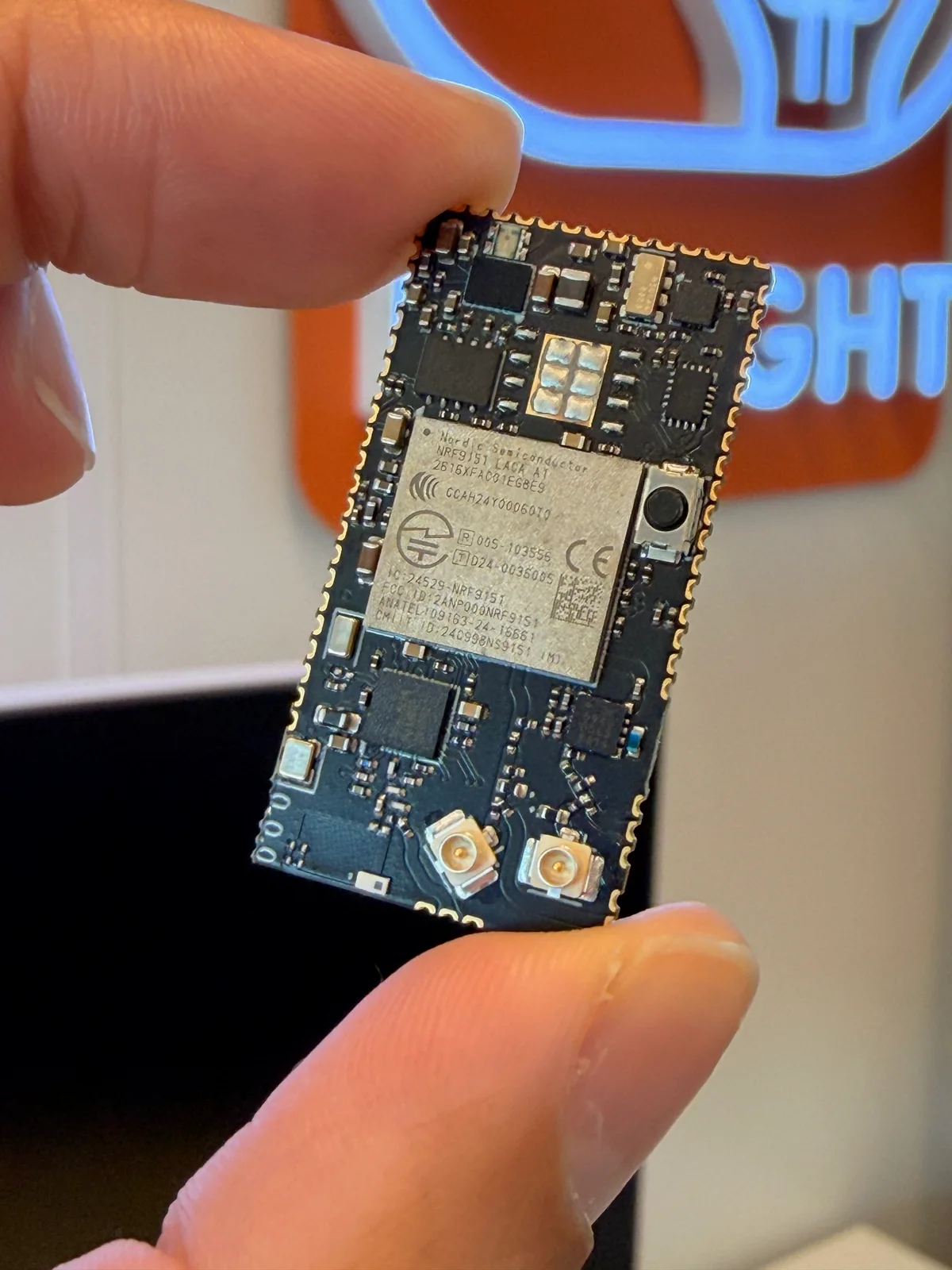
The nRF54LM20B is at the heart of CAS Edge AI Module. Its integrated Axon NPU accelerates suitable AI models on the device itself. A hardware foundation for pattern recognition, classification and anomaly detection in sensor data — built around your application.
The AI hardware is on board. Models, sensors and firmware are developed and validated for each application; no generic AI model comes preinstalled.
Connect the sensors your application needs through a custom carrier. Collect the data we use to train and test the model.
Run a suitable AI model on the LM20B. Local inference does not have to wait for a cloud connection.
Send a status, classification or event to your platform. You decide which data leaves the device.
The LM20B handles local processing. The nRF9151 connects results to the outside world, while the nPM1300 manages energy. Together they provide a foundation for a connected edge-AI product.
The edge-AI core
128 MHz Axon NPU for suitable AI inference, alongside a 128 MHz Cortex-M33 and RISC-V coprocessor. 2 MB NVM and 512 KB RAM for your embedded application.
Component informationConnects to the outside
LTE-M, NB-IoT and GPS/QZSS. IoT NTN and DECT NR+ are additional chip capabilities, with separate firmware and network requirements.
Component informationManages the energy
Charging, power path, 1.8 V buck and battery measurements. Firmware adapts charging settings and energy modes to the selected cell.
Component informationSpecifications from the hardware design and component documentation. Revision 0.0.0 is a development platform; chip capabilities are not automatically validated product features.
Preliminary specifications · hardware rev. 0.0.0
Module power consumption, RF performance and temperature range still require characterisation. CE/RED and other approvals must be assessed for the final product.
CAS means Connect and Sense: our development platform for connected products. From solar-powered tracking and vibration sensing to hardware for edge AI. We adapt the solution to your application.
A pattern, machine activity or an anomaly in sensor data. Tell us what you want to recognize, which measurements are available and where the device will operate. Together we scope the model, hardware and validation.
Discuss your AI application'%3e%3cpath%20d='M0.512578%2012.7977C0.512016%2014.8142%201.04302%2016.7831%202.0527%2018.5185L0.416016%2024.448L6.53152%2022.857C8.22299%2023.7706%2010.1181%2024.2494%2012.044%2024.2495H12.0491C18.4067%2024.2495%2023.582%2019.1162%2023.5847%2012.8067C23.586%209.74933%2022.3871%206.87435%2020.2089%204.71138C18.0311%202.54858%2015.1347%201.35686%2012.0486%201.35547C5.6902%201.35547%200.515297%206.48849%200.512672%2012.7977'%20fill='url(%23paint0_linear_1455_10349)'/%3e%3cpath%20d='M0.100313%2012.7941C0.0996563%2014.8831%200.649687%2016.9224%201.69537%2018.72L0%2024.8621L6.33478%2023.214C8.08022%2024.1582%2010.0454%2024.6561%2012.0451%2024.6568H12.0502C18.636%2024.6568%2023.9972%2019.3389%2024%2012.8035C24.0011%209.63629%2022.7591%206.65796%2020.5031%204.4175C18.2468%202.17731%2015.2468%200.942709%2012.0502%200.941406C5.46337%200.941406%200.102938%206.25862%200.100313%2012.7941ZM3.87291%2018.4104L3.63637%2018.0379C2.64206%2016.4691%202.11725%2014.6563%202.118%2012.7948C2.12006%207.36271%206.57544%202.94327%2012.054%202.94327C14.7071%202.94438%2017.2005%203.97062%2019.0759%205.83257C20.9512%207.69471%2021.9831%2010.1701%2021.9824%2012.8028C21.98%2018.2349%2017.5245%2022.6549%2012.0502%2022.6549H12.0463C10.2638%2022.654%208.51569%2022.179%206.99113%2021.2814L6.62831%2021.0679L2.86912%2022.0459L3.87291%2018.4104Z'%20fill='url(%23paint1_linear_1455_10349)'/%3e%3cpath%20d='M9.06383%207.83911C8.84014%207.34581%208.60473%207.33586%208.39202%207.32721C8.21783%207.31976%208.0187%207.32032%207.81977%207.32032C7.62064%207.32032%207.29711%207.39465%207.02364%207.69093C6.74989%207.98748%205.97852%208.70414%205.97852%2010.1617C5.97852%2011.6193%207.04848%2013.028%207.19764%2013.2259C7.34698%2013.4234%209.26323%2016.5103%2012.2981%2017.6978C14.8204%2018.6847%2015.3336%2018.4884%2015.881%2018.4389C16.4285%2018.3896%2017.6477%2017.7225%2017.8964%2017.0306C18.1453%2016.3389%2018.1453%2015.746%2018.0707%2015.6221C17.996%2015.4986%2017.7969%2015.4245%2017.4983%2015.2764C17.1997%2015.1283%2015.7317%2014.4115%2015.458%2014.3126C15.1843%2014.2138%2014.9853%2014.1645%2014.7861%2014.4612C14.587%2014.7573%2014.0152%2015.4245%2013.841%2015.6221C13.6669%2015.8201%2013.4926%2015.8448%2013.1941%2015.6966C12.8953%2015.5479%2011.9337%2015.2355%2010.7929%2014.2263C9.90523%2013.441%209.30598%2012.4712%209.1318%2012.1746C8.95761%2011.8784%209.11314%2011.7178%209.26286%2011.5702C9.39702%2011.4374%209.56155%2011.2242%209.71098%2011.0513C9.85986%2010.8783%209.90955%2010.7548%2010.0091%2010.5573C10.1088%2010.3595%2010.0589%2010.1865%209.98436%2010.0383C9.90955%209.89009%209.32933%208.42488%209.06383%207.83911Z'%20fill='white'/%3e%3c/g%3e%3cdefs%3e%3clinearGradient%20id='paint0_linear_1455_10349'%20x1='1158.85'%20y1='2310.61'%20x2='1158.85'%20y2='1.35547'%20gradientUnits='userSpaceOnUse'%3e%3cstop%20stop-color='%231FAF38'/%3e%3cstop%20offset='1'%20stop-color='%2360D669'/%3e%3c/linearGradient%3e%3clinearGradient%20id='paint1_linear_1455_10349'%20x1='1200'%20y1='2393.01'%20x2='1200'%20y2='0.941406'%20gradientUnits='userSpaceOnUse'%3e%3cstop%20stop-color='%23F9F9F9'/%3e%3cstop%20offset='1'%20stop-color='white'/%3e%3c/linearGradient%3e%3cclipPath%20id='clip0_1455_10349'%3e%3crect%20width='24'%20height='24'%20fill='white'%20transform='translate(0%200.941406)'/%3e%3c/clipPath%3e%3c/defs%3e%3c/svg%3e)